
ZImager#
ZImager provides three simultaneous optical imaging channels with separate qCMOS detectors. The September design uses a CaF₂ field lens, a common atmospheric-dispersion corrector (ADC), two dichroics, and three f/1.7 cameras.
Optical layout#
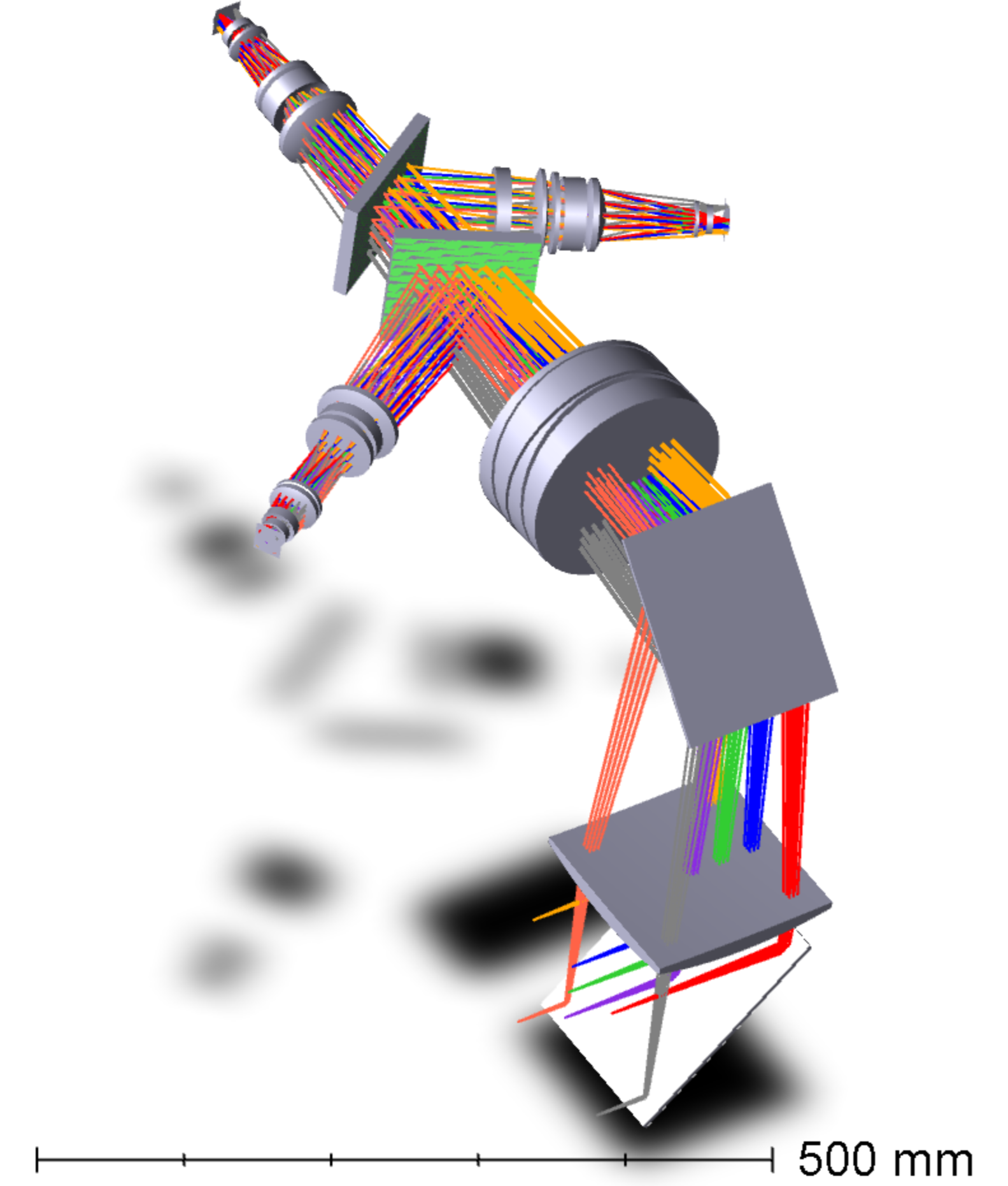
The optical render’s scale bar is 500 mm.
An insertable fold selects the imager path near the telescope focus. The field lens slows the beam to f/17.4 and reduces chief-ray angles through the downstream optics. The ADC precedes the channel split; each camera contains one asphere. The three detector heads rotate independently to remove field rotation.
Parameter |
Current design |
|---|---|
Optical channels |
300–400 nm; 400–820 nm; 820–1,000 nm |
Selectable middle-channel bands |
400–550, 550–690, or 690–820 nm |
Camera speed |
f/1.7 |
Detector |
ORCA-Quest 2 qCMOS, 4.6 µm pixels |
Pixel scale |
Approximately 0.05″/pixel; 0.0511″/pixel in the simulator |
Simulator detector format |
4,096×2,304 pixels per channel |
Simulator detector footprint |
Approximately 3.5′×2.0′ |
Field derotation |
Independent 360° rotation of each detector head |
Image quality and ADC#
The optical study reports an average geometric spot diameter of 0.035″ across fields, bands, and zenith angles. The design includes the atmosphere, telescope, ADC, and filters.
The ADC uses tilted CaF₂/Nikon 5859 Risley-prism pairs and is modeled over zenith angles of 0–60°. At 60°, the relative prism angle is 126°. The model assumes 4,207 m elevation, 610 mbar, 293 K, and 50% humidity; environmental variation remains to be evaluated.
Simulator model#
The ZImager branch routes light through three channel-specific optical paths to separate detector images, with independent exposure settings and a common ORCA-Quest QE curve. Its detector model uses 0.3 e⁻ read noise, 0.006 e⁻/s/pixel dark current, and a 7,000 e⁻ full well at −35°C.
The model’s rectangular detector footprint differs from the 1.7′×3.5′ footprint shown in the September optical deck. The final illuminated field and field overlap during detector rotation remain design checks.
Design work to close
Field and format: reconcile the deck’s 2k×4k / 1.7′×3.5′ sensor footprint and 2.25′ square layout label with the simulator’s 4,096×2,304 format. Establish the unvignetted footprint and common field through a full detector rotation.
Bands: reconcile the fixed i-band L1 requirement with the optical design’s 820–1,000 nm red channel; select the first-light middle-channel filters.
ADC and UV: thicken the CaF₂ prism edges; evaluate temperature, pressure, and humidity sensitivity; verify the Nikon i-line glass index model below its stated 326 nm limit down to 310 nm.
Camera completion: settle UV contacting fluid versus air spacing, consolidation of the adjacent VIS CaF₂ elements, NIR element thicknesses, filter tilt, and final aspheric surfaces. Confirm procurement lead times for sapphire, BaF₂, and specialty glass.
Image-quality bookkeeping: reconcile the deck’s 0.035″ average geometric diameter with its 1.4-pixel RMS-diameter summary, and carry the field- and wavelength-dependent PSFs into the simulator.
Sources
ZImager optical design: September 30, 2026, slides 1–12. The render is the original image from slide 3.
IRDB
origin/zimager, commitb60c2a5:ZShooter_IMAGER.yaml,ZShooter_IMDET.yaml, anddefault.yaml. This page describes the branch configuration; it does not substitute its detector footprint for a verified optical field.Requirements and calibration procedures define the imaging and registration work.